 Advanced Carbon PropellersLight is Right
E-Props : manufacturing, leading edge protection, balancing, tracking
E-PROPS propellers are manufactured entirely in France (South-East, Provence, near Sisteron). The team of 67 aeronautical engineers and technicians produces over 75000 carbon parts a year.
This page details five key aspects of that manufacturing process, to expand below: the RTM process and HCF technology that give E-Props carbon blades their strength and lightness; the two leading-edge protection options, Titanium or Nanostrength, depending on the propeller range; the care taken in balancing every propeller before shipment; the tracking tolerance, often misunderstood; and finally the avenues to explore if vibration is felt in flight.
1 — E-Props manufacturing processRTM process, carbon blades (HCF technology), carbon hubs and spacers, spinners, RFID/QR-code/KANBAN traceability, PALADIN (in-house ERP).
All E-PROPS parts — blades, hubs, spacers and spinners — are made of carbon and epoxy resin, designed to be both as lightweight as possible and stronger than necessary. This balance can only be achieved through control over the entire production chain, from raw materials to the finished part. Unlike most propeller manufacturers, E-Props does not depend on any external subcontractor or third-party software vendor for its production: the composite process, the finishing machines, and the traceability and ERP software that ties them all together are all developed and operated by E-Props' own teams.
RTM process (Resin Transfer Molding)
All E-Props parts — blades, hubs and spinners — are made using RTM (Resin Transfer Molding). This process is used by manufacturers such as Airbus and Boeing for some of the critical, ultra-light carbon parts on airliners, and is one of the best methods available for producing composite parts with large surface areas, complex shapes and smooth finishes.
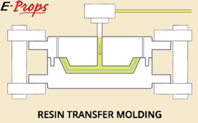
RTM offers several key benefits over alternative composite processes:
- very good surface quality
- very high fiber ratio
- a wide range of possible reinforcements
- large, long or complex shapes
- low environmental impact
- reduced manual labor
- no direct contact between operators and raw materials, which is far better for their health
The process itself follows a strict temperature cycle: curing the carbon parts under controlled heat improves their mechanical properties, in particular their strength, including under high-temperature conditions.
In practice, the carbon braid is first cut then slid over a preformed foam core, like a sock (see the HCF process below); the assembly is placed in the mold, which is then closed and injected with epoxy resin under pressure, before following the temperature curing cycle. After demolding, every part is precisely weighed at multiple stages of manufacturing — for example, seven separate weighings are performed for a single ultralight/aircraft propeller — then goes through dimensional control and finishing on E-Props' 8-axis machining centres, presented in detail on the Workshops and Production Equipment page.
Carbon blades: the HCF (Helical Continuous Fibers) process
All E-Props blades are made of carbon braid and epoxy resin. Carbon offers an excellent compromise between rigidity and weight, and using a single base material is far superior to mixing materials — for instance blending fiberglass with carbon, a common way of saving on carbon, which is significantly more expensive than fiberglass.
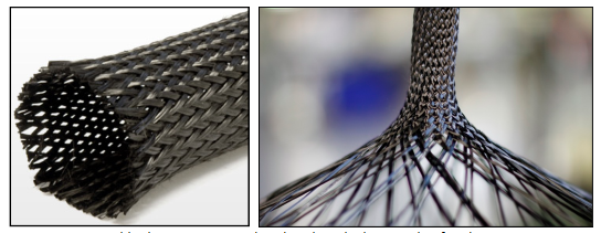
The HCF process (Helical Continuous Fibers), developed specifically by E-Props, gives the 100% carbon + epoxy blade exceptional strength from leading edge to trailing edge and from root to tip. Unlike the "half-shell" process used by most composite propeller manufacturers, the carbon fibers are continuous between the upper and lower surfaces: the braid is woven like a sock over the blade. This greatly increases mechanical strength — there is no risk of leading-edge delamination, and no cracking of the blades or the hub.
Building a strong carbon part means maximizing the fiber content and minimizing the resin content: fiber is roughly 50 times stronger than resin.
| Material | Tensile strength |
|---|---|
| Carbon fiber | 4,000 MPa |
| Fiberglass fiber | 2,600 MPa |
| Epoxy resin | 80 MPa |
E-Props parts have an exceptionally high carbon fiber ratio of 63%, compared with around 40% for a typical two-piece glued half-shell fiberglass blade — a decisive gap, both because of the ratio itself and because carbon fiber is intrinsically stronger than glass fiber.
Epoxy resin is the resin of choice in aeronautics: it offers very good mechanical and thermal properties, high fatigue resistance, good dimensional stability, good chemical performance and, above all, excellent adhesion to carbon fibers. The epoxy resin used by E-Props also includes a high-resistance UV additive (UVA and UVB).
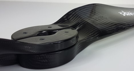
Key features of blade manufacturing include:
- a foam core with an internal D-Box spar
- on the ultralight/LSA range, a titanium ring insert inside the blade foot
- 100% carbon construction — no metallic parts, hence no galvanic corrosion
- external leading-edge protection (see section 2 below)
- a unique reference number on every blade, with an embedded RFID chip, for full traceability
- sets of blades balanced together to a strict static-moment tolerance
Carbon hubs and spacers
E-Props hubs are made of carbon fabric and epoxy resin. Carbon fabric offers high stiffness, high tensile strength, low weight, high chemical resistance, high temperature tolerance and low thermal expansion. E-Props uses only carbon fabric supplied by major aerospace-industry manufacturers: more expensive, but offering far better quality and traceability. The RTM process is also used to mold the hubs, which are extremely strong and very light.
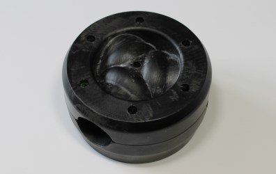
Key features of hub manufacturing include:
- 100% carbon fabric — no metallic parts, hence no galvanic corrosion
- a unique reference number on every hub component, with an embedded RFID chip, for full traceability
- the hub is balanced together with its matching set of blades, to avoid vibration of the assembled propeller
Spinners
E-Props spinners are made of carbon fabric and epoxy resin, also molded using the RTM process. They are very light and very robust.
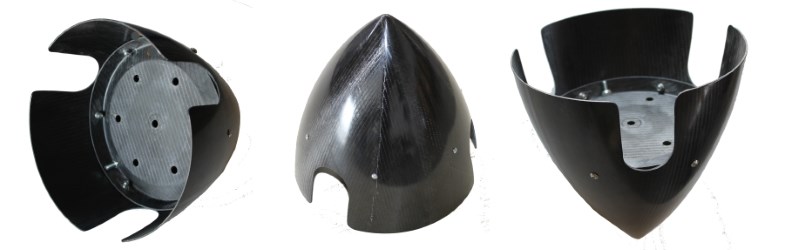
Key features of spinner manufacturing include:
- 100% carbon fabric construction
- a unique reference number on both the spinner and its flange, with an embedded RFID chip, for full traceability
- the spinner and flange are balanced together; where necessary, a small screw is fixed to the flange for perfect balancing — this screw must never be removed
- spinners are polished to a very fine finish, with no paint or varnish applied at the factory
Traceability: RFID, QR-code, KANBAN
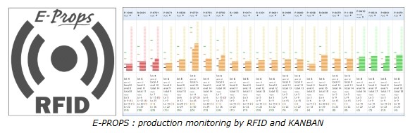
Every part — blade, hub component or spinner — carries its own RFID chip and/or an individual printed QR code, and a unique reference number, embedded from the earliest stage of manufacturing. Production itself is monitored using RFID and KANBAN methods, which optimize manufacturing quality, secure and streamline supplies, and provide real-time follow-up of the production process. Together, they give E-Props full traceability of every manufacturing step, and a set of reliable production indicators.
PALADIN — in-house ERP
Since 2014, E-Props has developed and operated its own Enterprise Resource Planning (ERP) system in-house: PALADIN. As E-Props works towards EASA POA (Production Organisation Approval) Part-21G certification — which requires perfectly complete traceability of every part and every process — PALADIN has been continuously extended to meet this requirement, and is now in daily use across the whole factory.
Developing and maintaining a full ERP system entirely in-house is unusual for a company of E-Props' size, and represents a major strategic asset for the team: a dedicated group of four in-house software engineers builds and continuously improves PALADIN, keeping it tailored exactly to E-Props' own RTM/HCF manufacturing process rather than adapting production to the constraints of a generic, off-the-shelf ERP package.
PALADIN covers, in a single integrated system:
- production planning and scheduling
- manufacturing follow-up and real-time tracking of every part's position on the factory floor throughout the production phases
- purchase requests and supplier order follow-up
- stock and inventory management
- complete traceability of parts and materials, by batch and by individual serial number, via RFID chips embedded in every component
- tracking of parts through every CNC machine step — resin injection, curing ovens, dimensional control and finishing
- quality control records for every part and every production step
- allocation of parts and assemblies to customer orders
- sales administration: quotations, invoicing and order management
- shipment tracking
- accounting, and cost accounting — the calculation of the real production cost of every part
- human resources: staff training records and time-and-attendance
- equipment management and maintenance follow-up for all production machines
- monitoring of factory safety systems, such as sprinklers and alarms
2 — Leading edge protection: Titanium or Nanostrengthtitanium leading edge protection (V20 range), Nanostrength® protection (V12 range and fixed-pitch propellers), additional protection with polyurethane tape.
The leading edge of propeller blades needs reinforced protection against impacts from stones or other projectiles, and sometimes against erosion caused by rain and sand.
Titanium leading edge protection (V20 range)
Since October 2019, E-Props propellers in the V20 range have a leading edge protected with a Titanium shield, 5/10 mm thick and 40 cm long (on propellers with a diameter greater than 170 cm). E-Props uses a superplastic Titanium forming process, similar to the one used for the leading edges of the Rafale fighter jet.
Titanium is the ideal material for blade protection, thanks to its mechanical characteristics:
- specific strength outclassing Aluminum and Steel
- expansion and elasticity coefficients close to the carbon-epoxy composite of E-Props blades
- exceptional corrosion resistance, particularly in marine environments
- twice as light as Steel or Inconel
The Titanium used by E-Props is forged at high temperature in special dies. Everything is manufactured in E-Props' workshops in Sisteron. If the Titanium shield is damaged, E-Props can replace it without having to change the whole blade.
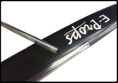
Blades with a Titanium leading edge (V20 range) are manufactured specifically for it: the mold includes a dedicated location, matching the blade profile, where E-Props bonds the shield. Blades in the V12 range do not include this location and therefore cannot receive a Titanium shield (see Nanostrength below).
Titanium has the same expansion coefficient as the carbon in the blades, so it expands at the same rate and does not detach. Across hundreds of thousands of blades equipped this way, for aircraft and drones, E-Props has never had a single instance of shield detachment.
In marine environments, no galvanic corrosion can occur, unlike what happens between aluminum and carbon. Titanium leading edge protection is therefore the best solution for seaplanes: E-Props equips, among others, the ICON A5, Super Petrel, Aventura, Seamax, Borey, and many other floatplanes.
Nanostrength® protection (V12 range and fixed-pitch propellers)
All E-Props carbon propellers that are not Titanium-shielded (paramotor propellers, V12 range) have a leading edge protected with a Nanostrength® impact additive (an ARKEMA product — nanostructured additives with high kinetic energy absorption capacity) built into the epoxy resin.
At E-Props, this protection is injected all along the leading edge during blade manufacturing, through the RTM process. It is therefore fully integrated into the blade, with no risk of detachment, material incompatibility or galvanic corrosion, and with the blade profile perfectly respected. It is more impact-resistant than a 5/10 mm Steel or Inconel shield, and much easier to repair.
Nanostrength® protection was originally developed for Rotax 914-powered aircraft equipped with E-Props since 2008, as well as for propellers fitted to aircraft and microlights in Africa, operating from unprepared laterite runways.
Many E-Props customers prefer this integrated protection to a bonded Steel or Inconel shield, for several reasons: it is built into the blade, with no risk of coming loose; there is no Steel or Inconel, hence no galvanic corrosion risk; the reinforcement runs the full length of the leading edge; there is no added mass at the blade tip, hence a lower moment of inertia; and the leading edge can easily be repaired, even after a major impact (a case where a metal shield — or even the whole blade — would need replacing): any pilot can carry out the repair themselves, using an E-Props repair kit.
Additional protection: polyurethane tape
In very specific use cases — seaplanes and amphibious microlights, very long flights in heavy rain (monsoon-type conditions) at high engine RPM, or "barefoot" paramotor flying just above water and beach (E-Props does not recommend this kind of extreme flying) — it can be worthwhile to add extra protection to the leading edge of blades that are not Titanium-shielded.
For these cases, E-Props recommends applying a polyurethane protective tape. Made from a very high-performance elastomer, this material is particularly resistant to erosion, abrasion, perforation, minor impact damage and tearing. Its formula is also UV-resistant; its thickness is 0.36 mm. The tape model chosen by E-Props is used on certified helicopter blades.
This protective tape has no impact on the blades' aerodynamic performance: the numerous tests carried out by the E-Props team all show no measurable performance difference between a blade fitted with the tape and one without. It is transparent, adhesive on one side only, and can be painted or applied over already-painted surfaces. Its relative rigidity makes it very easy to apply and to replace. This material is available in the E-Props shop, in kits of various lengths and widths.
3 — Propeller balancingwhy E-Props propellers are so well balanced, balancing and static moment, dynamic balancing.
E-Props propellers are renowned for their light weight, low moment of inertia and perfect balance.
Why are E-Props propellers so well balanced?
The lighter a propeller is, the easier it is to achieve good balancing. Rotax recommends a balancing tolerance of 0.5 g/m; at E-Props, the target tolerance is 0.2 g/m, to avoid vibration and guarantee smooth, comfortable operation.
On geared engines such as Rotax, the propeller is mounted on the gearbox flange, and the bearing / shaft / any spacer assembly inevitably has a slight form defect. For a typical form defect of 0.1 mm, the resulting imbalance depends directly on the propeller's mass:
| Propeller mass | Resulting imbalance | Vs Rotax tolerance (0.5 g/m) |
|---|---|---|
| 2,000 g | 0.2 g/m | within tolerance |
| 6,000 g | 0.6 g/m | out of tolerance |
| 12,000 g | 1.2 g/m | far out of tolerance |
When the imbalance generated by form defects exceeds 0.5 g/m — which is very often the case among E-Props' competitors — some propellers on the market require dynamic balancing on the aircraft after every mount/dismount (see below). This is not the case for E-Props propellers, which tolerate these form defects well thanks to their light weight.
They have integrated carbon centering pins and spacer
Competing propellers use steel centering pins and aluminum spacers, which increase mounting dispersion (centering / coaxiality error). E-Props propellers have carbon centering pins built into a carbon spacer: besides saving 125 g, these carbon pins reduce play and improve mounting precision.
The E-Props carbon spacer is 13 times lighter than a conventional aluminum spacer: 1.5 g/mm versus 20 g/mm. For a 120 mm spacer, for example, the traditional aluminum model weighs 2,165 g versus only 180 g for the E-Props carbon spacer — a weight saving of 1.985 kg.
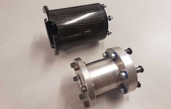
The E-Props carbon spacer avoids the form defects associated with stacked spacers, fastener play and centering pins, greatly simplifying propeller balancing.
They are manufactured in very large series, and all balanced before shipping
E-Props' annual production is over 75000 carbon parts a year. Each blade model is produced in large series, making it easier to obtain blades with a very similar static moment. Every propeller is then carefully balanced by the E-Props team — blades, hub and spacer together — on high-precision digital balancing benches, designed and built in-house. The software enforces a maximum tolerance of 0.2 g/m, and quality control must validate this value before authorizing shipment.
Balancing and static moment
In a propeller, the blades do not necessarily need to have the same mass. What counts for perfect balancing is the distribution of mass along the length of the blade: the static moment, the sum of the products of surface areas by the lever arm normal to the reference axis.

The masses P1 and P2 of each blade act at centers of gravity G1 and G2, which are not necessarily at equal distances from the propeller's center of rotation O. Balancing must be carried out to achieve the relation P1 × d1 = P2 × d2. The maximum E-Props tolerance for static moment is 0.2 g/m.
Real example, for a 150 cm 2-blade propeller for a 40 hp engine: blade #43806 weighs 348.58 g with a static moment of 83.43 g/m; blade #48875 weighs 350.43 g with a static moment of 83.53 g/m. The masses differ by 1.85 g, but the static moment difference is only 0.1 g/m, within tolerance: this propeller is perfectly balanced.
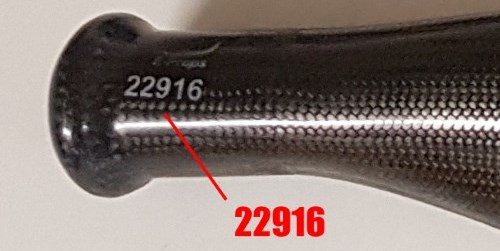
Every E-Props blade carries a unique serial number, visible on the blade and recorded in its internal RFID chip. Each blade is paired with one (or more) other blade: it is this paired set that is balanced. Mounting blades that are not paired together produces an unbalanced propeller. The serial numbers intended to go together are shown on the invoice and delivery note; if in doubt, the E-Props team can confirm this by email, or the propeller can be sent back for a balance check. Never fly with an E-Props propeller whose blades are not paired.
Dynamic balancing: is it useful?
When vibrations appear, it can be tempting to check whether the propeller's balance remains correct once mounted on the engine and spinning (dynamic balancing). Because E-Props propellers are particularly light, the precision of their positioning on the engine flange degrades the overall balance only very slightly: the E-Props team has tested dynamic balancing on its models without being able to measure any difference or bring about any improvement.
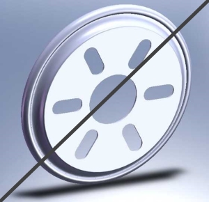
Devices designed to restore the dynamic balance of rotating propellers have existed since the 1940s. On a geometrically sound engine with a propeller that is well balanced statically, this type of device is unnecessary — merely expensive and heavy — and would in any case need to be redone after every mount/dismount of the propeller.
4 — Tracking
"Tracking" is the difference in longitudinal position from one blade tip to the next. Tracking discrepancies are often found on wooden propellers, which are manufactured and/or finished by hand. On propellers manufactured in series, coming out of identical, non-adjustable molds, this phenomenon does not appear, or barely does.
Blades of the same E-Props model come out of the same mold: they have exactly the same geometry, and their finishing is then carried out by numerically controlled machines. E-Props blades from the same mold therefore show no tracking. On E-Props propellers, the maximum tracking tolerance is 15 mm.
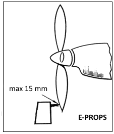
Tracking measured at the propeller can also come from elsewhere: a gearbox plate that is not perfectly flat or parallel, asymmetrical engine mounts, tightening without a torque wrench... If your propeller does not generate vibration, the tracking value measured is of no importance whatsoever, even if it exceeds 15 mm.
5 — Propellers and vibrationsorigin — the propeller, origin — the engine, origin — the aircraft, diagnosis.
E-Props propellers are known for generating very little vibration: they are very light, and all balanced on a dynamic electronic bench. A pilot may nevertheless occasionally feel vibrations in flight. These may originate from the propeller, the engine and/or the aircraft. Here are a few pointers for identifying, and possibly resolving, this kind of issue.
Origin: the propeller
First, make sure that all the components of the propeller are indeed the original ones: mixing in parts from another propeller would break the balancing. Every component carries a unique serial number, shown on the delivery note, the invoice and the propeller's identification sheet.
Every propeller is balanced together with its blades, its two-part hub (HH1&2 on the ground-adjustable range, HLP&HHP on the variable-pitch range) and its spacer; cones and their plates are balanced separately.
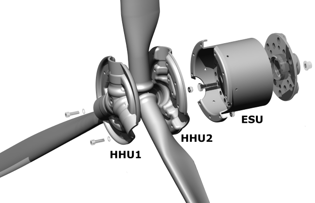
On E-Props ground-adjustable-pitch propellers (Durandal and Excalibur ranges), a significant pitch difference between blades can generate vibration: the maximum tolerance on these models is 0.3°. This is the first check to make in case of vibration after the initial mounting of a ground-adjustable propeller — the measurement method is explained in the manual, on the website, on the propeller's identification sheet, and in video form.
On variable-pitch (in-flight) propellers, any vibration may come from the position of the pushrods, which must remain paired with their blades using color-coded stickers — assembly must strictly follow the manual and the videos. Next, check the tightening of the mounting bolts on the engine flange with a torque wrench: on initial mounting, a slight settling of the carbon is possible, and uneven tightening can lead to vibration. The cone and its plate, balanced together, must be mounted respecting their pairing; if the cone is painted after delivery, its balance must be rechecked after painting. If accessories (cone, plate, extension) are not supplied by E-Props, they may be poorly balanced and require rebalancing of the whole assembly.
Finally, propellers produce a helical airflow that can interact with the airframe or other aircraft surfaces: changing propeller can alter this flow and generate vibrations different from those felt previously.
Origin: the engine
Fitting an ultra-light, well-balanced E-Props propeller can reveal engine vibration ranges that were previously masked by the vibrations of the old propeller.
Around 1,800-2,000 rpm, the main cause is usually poor carburetor synchronization: as soon as an engine has at least two carburetors, they must be synchronized to balance pressures and flow rates, with throttle valves positioned identically on their idle stops. Around 2,500 rpm, it may instead be an idle jet that is not leaning the mixture enough: check the setting of the air-mixture screw (the small brass screw on the left side of the carburetor).
The reduction gearbox can also generate vibration if there is excessive play between the gears — a heavy propeller with a high static moment also wears out gearboxes faster. Engine silent-blocks, if too soft, too rigid, worn, or counterfeit, can also be the cause: they should then be replaced.
Origin: the aircraft
Vibrations felt in flight can also originate from the aircraft itself, and can become more noticeable after a piece of equipment is changed. A vibration frequency from the engine or the propeller can resonate with a natural frequency of the airframe (wings, tail) and amplify the phenomenon. Poorly adjusted or worn flight controls, or loose engine cowling fasteners, can also transmit vibration. Wheel rotation can generate imbalance too: on some aircraft, such as the MCR, the nose wheel must be braked on takeoff to avoid vibration, particularly right after liftoff.
Diagnosis
Before worrying about a vibration that appears after a propeller change, it is essential to establish a diagnosis: at what engine RPM does it appear (idle, takeoff, climb, cruise, full throttle, descent)? Does it vary with airspeed or flight configuration? Where is it most noticeable (seat, flight controls, instruments)? Next, inspect the propeller (serial numbers, position of components, pitch difference, tightening), the engine mounts and cowlings, carburetor synchronization and the idle jet, and check for play in the flight controls and linkages. If nothing obvious appears, some maintenance shops have equipment to measure vibration frequencies and compare them to the characteristic frequencies of the engine and its components; if another propeller is available, mounting it also shows whether the phenomenon reoccurs.


 Paramotor propellers
 Drone & UAV propellers
 E-Props blog
 Facebook
 YouTube
 Instagram