Design hélices - Logiciel LUKY - Moment d'Inertie - Performances - Changer d'hélice ?
Le bureau d'études E-PROPS est dirigé par Jérémie BUIATTI.
Il est composé à ce jour de 18 ingénieurs et techniciens aéronautiques, qui réalisent les calculs théoriques, la modélisation, la mise au point des prototypes, puis les expérimentations au banc au sol et en vol.
Jérémie Buiatti a développé le logiciel spécifique LUKY pour concevoir des hélices innovantes ultra-performantes, et maîtrise tous les aspects techniques nécessaires à la mise au point d'hélices ultra-performantes.
1 - Logiciel E-Props LUKY
2 - Conception hélices / Essais / Théorie / Moment d'inertie
3 - E-Props: Rendement / Légèreté / Réduction de bruit
4 - Pourquoi changer d'hélice ?
Le logiciel LUKY permet de modéliser le comportement d'une hélice E-Props sur un moteur donné, d'un point de vue aérodynamique et mécanique, y compris l’analyse vibratoire et le calcul de la durée de vie.
Il permet au bureau d'études E-Props de mettre au point des profils de pales adaptés à chaque ensemble avion - moteur - usage.
=> Voir description ici: LOGICIEL LUKY
Ce logiciel utilise une modélisation de type Ligne Portante pour la vitesse d'exécution, de façon à permettre l'exploration du domaine des hélices possibles à l'aide d'un algorithme évolutionnaire (métaheuristique), afin d'automatiser la recherche de solutions hélices (dimensionnement mécanique et aérodynamique) à un problème donné.
Ce sont des milliers d'heures de code et de tests par des ingénieurs très spécialisés qui ont été nécessaires pour mettre au point ce logiciel.
LUKY est une avancée exceptionnelle pour la mise au point d'hélices tout aussi exceptionnelles.
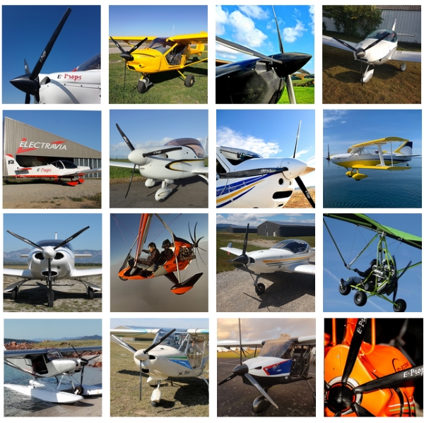
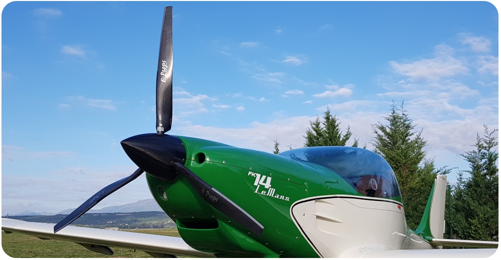
Les hélices E-PROPS sont étudiées pour offrir le meilleur rendement possible, tout en étant à la fois ultra-légères et extrêmement solides.
✗ La méthode d'optimisation des hélices est un procédé itératif complexe.
=> Voir description ici: CONCEPTION des HELICES E-PROPS
✗ Il est fondamental de tester les hélices pour valider les calculs et modélisations et comparer les performances avec d'autres hélices.
=> Voir description ici: ESSAIS des HELICES E-PROPS
✗ Pour comprendre le fonctionnement d’une hélice, il est essentiel de comprendre les lois issues de la physique expérimentale.
=> Voir ici: PROPULSION: UN PEU DE THEORIE
✗ Le moment d'inertie [MOI] est une donnée très importante pour les hélices.
=> Voir explications ici: HELICES ET MOMENT D'INERTIE
=> Rotax Service Instruction: Propeller mass moment of inertia for ROTAX
✗ Influence de l'inertie de l'hélice
Jérémie Buiatti, concepteur des hélices E-PROPS, s'est intéressé de près à ce qui se passe entre le moteur et l'hélice. Il a rédigé un article pour les publications du Colloque de Cachan 2016 organisé par l'association INTER ACTION (Association de Sauvetage Créatif du Savoir Aérotechnique).
=> Voir son article ici: "Les pistons tapent, le réducteur trépasse"
✗ Depuis les débuts de l'aviation, les hélices ont beaucoup évolué. Les E-Props sont des hélices de 3ème génération.
=> Voir ici: LES HELICES DE 3EME GENERATION
✗ E-Props : des hélices à rendement exceptionnel
Les hélices E-PROPS ont des profils très particuliers et des designs spécifiques afin de réduire la traînée des pales, et donc d'obtenir la meilleure poussée possible.
=> Voir description ici: RENDEMENT HELICES E-PROPS
✗ E-Props : des hélices ultra-légères
Les E-Props sont les hélices les plus légères au monde.
Pour comprendre pourquoi ces hélices sont ultra-légères, et pourquoi la légèreté de cet équipement est essentielle :
=> Voir explications ici: E-PROPS: DES HELICES ULTRA-LEGERES
✗ E-Props : réduction des nuisances sonores
Depuis 2008, l'équipe E-PROPS réalise des recherches approfondies sur le bruit des hélices et sur des solutions pour le réduire autant que possible.
=> Voir description ici: REDUCTION DU BRUIT HELICES
Quelques minutes pour se poser de bonnes questions concernant cet équipement fondamental.
=> Et voir des réponses ici: POURQUOI CHANGER D'HELICE ?
Il est composé à ce jour de 18 ingénieurs et techniciens aéronautiques, qui réalisent les calculs théoriques, la modélisation, la mise au point des prototypes, puis les expérimentations au banc au sol et en vol.
Jérémie Buiatti a développé le logiciel spécifique LUKY pour concevoir des hélices innovantes ultra-performantes, et maîtrise tous les aspects techniques nécessaires à la mise au point d'hélices ultra-performantes.
1 - Logiciel E-Props LUKY
2 - Conception hélices / Essais / Théorie / Moment d'inertie
3 - E-Props: Rendement / Légèreté / Réduction de bruit
4 - Pourquoi changer d'hélice ?
1 - Logiciel E-Props LUKY
Le logiciel LUKY permet de modéliser le comportement d'une hélice E-Props sur un moteur donné, d'un point de vue aérodynamique et mécanique, y compris l’analyse vibratoire et le calcul de la durée de vie.
Il permet au bureau d'études E-Props de mettre au point des profils de pales adaptés à chaque ensemble avion - moteur - usage.
=> Voir description ici: LOGICIEL LUKY
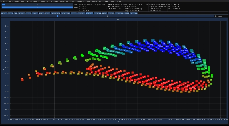
Ce logiciel utilise une modélisation de type Ligne Portante pour la vitesse d'exécution, de façon à permettre l'exploration du domaine des hélices possibles à l'aide d'un algorithme évolutionnaire (métaheuristique), afin d'automatiser la recherche de solutions hélices (dimensionnement mécanique et aérodynamique) à un problème donné.
Ce sont des milliers d'heures de code et de tests par des ingénieurs très spécialisés qui ont été nécessaires pour mettre au point ce logiciel.
LUKY est une avancée exceptionnelle pour la mise au point d'hélices tout aussi exceptionnelles.
2 - Conception hélices / Essais / Théorie / Moment d'inertie
Les hélices E-PROPS sont étudiées pour offrir le meilleur rendement possible, tout en étant à la fois ultra-légères et extrêmement solides.
✗ La méthode d'optimisation des hélices est un procédé itératif complexe.
=> Voir description ici: CONCEPTION des HELICES E-PROPS
✗ Il est fondamental de tester les hélices pour valider les calculs et modélisations et comparer les performances avec d'autres hélices.
=> Voir description ici: ESSAIS des HELICES E-PROPS
✗ Pour comprendre le fonctionnement d’une hélice, il est essentiel de comprendre les lois issues de la physique expérimentale.
=> Voir ici: PROPULSION: UN PEU DE THEORIE
✗ Le moment d'inertie [MOI] est une donnée très importante pour les hélices.
=> Voir explications ici: HELICES ET MOMENT D'INERTIE
=> Rotax Service Instruction: Propeller mass moment of inertia for ROTAX
✗ Influence de l'inertie de l'hélice
Jérémie Buiatti, concepteur des hélices E-PROPS, s'est intéressé de près à ce qui se passe entre le moteur et l'hélice. Il a rédigé un article pour les publications du Colloque de Cachan 2016 organisé par l'association INTER ACTION (Association de Sauvetage Créatif du Savoir Aérotechnique).
=> Voir son article ici: "Les pistons tapent, le réducteur trépasse"
✗ Depuis les débuts de l'aviation, les hélices ont beaucoup évolué. Les E-Props sont des hélices de 3ème génération.
=> Voir ici: LES HELICES DE 3EME GENERATION
3 - E-Props: Rendement / Légèreté / Réduction de bruit
✗ E-Props : des hélices à rendement exceptionnel
Les hélices E-PROPS ont des profils très particuliers et des designs spécifiques afin de réduire la traînée des pales, et donc d'obtenir la meilleure poussée possible.
=> Voir description ici: RENDEMENT HELICES E-PROPS
✗ E-Props : des hélices ultra-légères
Les E-Props sont les hélices les plus légères au monde.
Pour comprendre pourquoi ces hélices sont ultra-légères, et pourquoi la légèreté de cet équipement est essentielle :
=> Voir explications ici: E-PROPS: DES HELICES ULTRA-LEGERES
✗ E-Props : réduction des nuisances sonores
Depuis 2008, l'équipe E-PROPS réalise des recherches approfondies sur le bruit des hélices et sur des solutions pour le réduire autant que possible.
=> Voir description ici: REDUCTION DU BRUIT HELICES
4 - Pourquoi changer d'hélice ?
Quelques minutes pour se poser de bonnes questions concernant cet équipement fondamental.
=> Et voir des réponses ici: POURQUOI CHANGER D'HELICE ?